Links
Tags
Building a Custom Flight Controller for an Airbus A320
Continuing on from my Christmas Blog Post series, this one might very well be the start of building an A320 home cockpit but I make no promises here. One might even call it ramblings of a software developer who has discovered the hobby of 3D printing.
A trip down memory lane...
Among my earliest childhood memories around the Amstrad CPC6128 is one of my favourite games - Acro Jet. It's not a particularly interesting simulator to retrospect on, but the mind of a 4-5 year old can be quite powerful. Neither were F-16 Fighter for the Sega, Top Gun on the Nintendo Entertainment System, and any of the other many flight games on early 8-bit computers and consoles. Fast forward some 5 or 6 years and Microsoft Flight Simulator for Windows 95 was the new hotness. Armed with the Australian Scenery Pack, one could now fly under Sydney Harbour Bridge and... that's about it. Suffice to say, the complexities of aircraft never really hit home - nor could I ever land the planes, no matter the tutorial.
While at university, I saw Flight Simulator X in the bargain bin at one of our common game stores. It was the Accelerated pack, with manuals and all the glossy artwork. In there were several airliners and even though Melbourne Airport was pretty plain, it certainly resembled it more-so than the earlier games. What really enticed me to look at it was the multiplayer aspect - having the ability to be ATC or communicate with someone playing the ATC role. I would go on to play on and off for several years learning bits and pieces - but never taking it too seriously.
Some time around 2014, I had come across some YouTube videos on an Airbus A320 modification for Flight Simulator X. I hadn't looked into Prepar3d or any of the other flight simulators at the time, but this video would describe in detail how to do a cold start, key in your flight path, fuel planning and had some pretty impressive sounds and realism - compared with the stock A320 anyway. This got me interested as it was presented in a very palatable way. Checklists, flying and landing. I would soon after buy the aircraft and learn how to fly the A320 and have a lot of fun doing so for many years to follow. I've been through other simulators as well, including the defunct Flight Sim World, but suffice to say up to the Microsoft Flight Simulator 2020 launch, it's a plane and game I would return to time and time again.
When Flight Simulator 2020 finally released, I had a few weeks to play before my son was born. It was incredible. The stock aircraft were pretty well featured, if not a bit too easy to fly and the scenery was substantially improved - particularly for Sydney Airport (I'd purchased several airports over my time in FSX to improve realism). But... when you start building up those flight hours, get random crashes - it can leave a sour taste behind. Enough at least that I hadn't really played it for over a year since picking it up recent weeks again.
Some 100GB update later, and I note that most of my modifications have been removed, broken or replaced and unfortunately it felt like I was at step 1 all over again (this game has a serious problem in having many tools to modify the game). I remembered somewhere along the line, an open source effort to replicate the Airbus A320 was underway and thought I'd go and check it out. This didn't go so well - involving a total re-install of the game at a further 150GiB. After getting it all up and running again - with the A32nx mod installed (and of course, with a few liveries) - I'm ready to check out where I left things.
Comparing Flight Simulator X (and Aerosoft A320 mod) to Flight Simulator 2020 (and A32nx mod), you'll immediately notice a few things:
- The graphics in FS2020 are incredible compared to FSX - the scenery, motion, etc... feels a heck of a lot more realistic.
- The camera itself is also tilting, I guess just as your head would in a real aircraft.
For #2, this presents a real problem when trying to set any of the aircraft's flight control unit controls - because as you're trying to set an altitude while scrolling your mouse wheel, you may - due to motion - start changing heading, turning off controls, or setting your vertical speed for a nosedive. Suffice to say, this level of "realism" is completely useless for functionally while playing the game.
I've always wanted to build a home cockpit of sorts - there'd be a number of caveats of course. It would have to be compact and modular enough to store away when not in use. It'd also have to be for an aircraft I fly a lot. I'd want it to be familiar enough - but no need to be a perfect replica (I'm not a pilot after all, this is purely for fun) and I'd have to have fun building it as well. Suffice to say, the issue of motion annoys me so much that turning it off removes that feeling of realism so that really leaves me with building a modular set of flight controls.
Building a home cockpit is as old as Flight Simulators themselves, so there's a lot of material around on how to build one. Two of my favourite ones include The Warthog Project and Heli Mech who builds a Boeing 737 cockpit. The latter channel goes through how to build a lot of panels and components a number of different ways and his style has given me a few ideas on how I could similarly approach an Airbus A320 variant - at least in appearance. Over time, I'm sure I'll be adding a CNC machine to my collection but until then, I want to exhaust what it is that I can build using stuff I already own before investing in more garage clutter.
What can I 3D Print?
Heli Mech recently released a video using mostly off the shelf components and some 3D printing on a printer that has a much larger print bed than I do. It would be fairly easy to copy this design and Airbus-ify it, but if at all possible - I'd want to try and get it backlit (this design doesn't) and using custom components to mimic the Korry switches instead of using the KD2 buttons this guy uses. There are several videos on YouTube that make use of Laser cutters and Acrylic to cut out 3 plates - usually a White layer, and a couple of transparent layers that will be painted and etched into giving a professional looking finish to a panel. To get the equipment to do this will set you back a good $1,000 after all is said and done - so to start out, I'd like to see how far I can take this particular project to get an acceptable result.
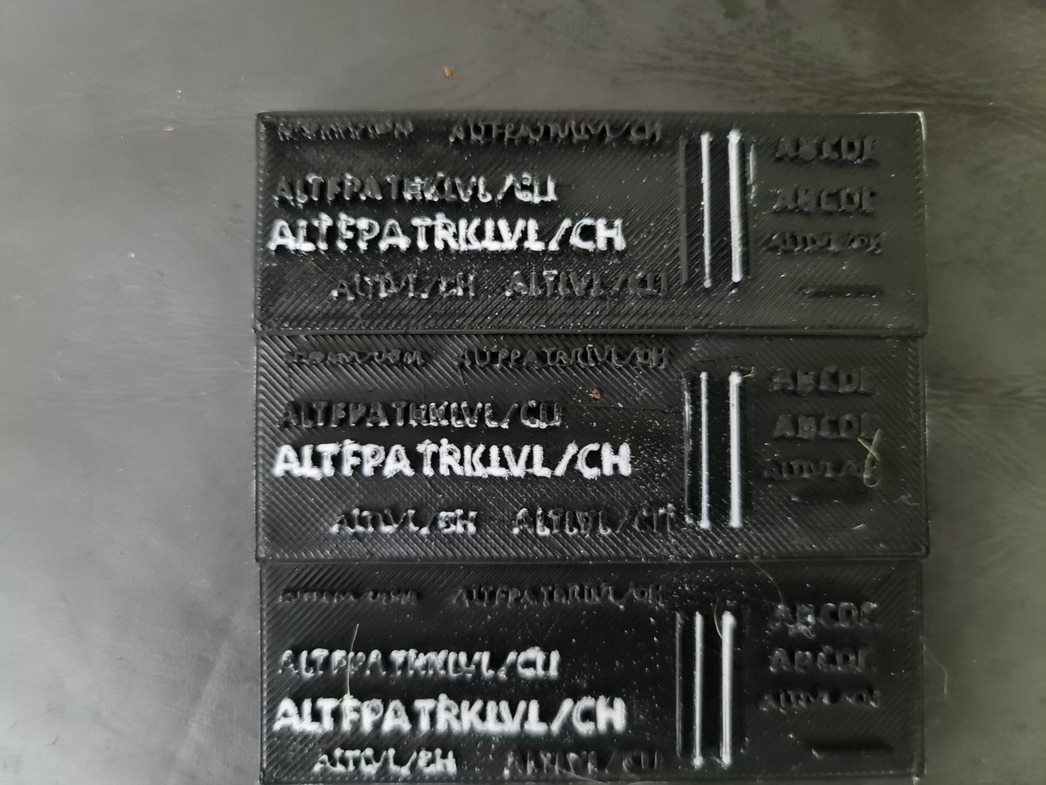
To get started, I really need to see how I'm going to get light through plastic. I begin by designing a 90mm x 90mm canvas at different heights, with text all over them to see what might render well. I've chosen variations between 2mm and 5mm - understanding that 5mm is going to be far too large, but if the text is legible - this might be a trade off I need to make. I then load this into the 3D Printing software and take a look at how the layers are going to print. Obviously the smaller text is going to be tricky - but with a calibrated printer it could be made to work (after the 6 months it's had pushing out Christmas decorations, I'm sure it's anything but level at the moment).
Using some scrap white filament, I'm printing out at 100% infill as the light will need to "push" through and something tells me that light isn't going to be too happy if it's not dense enough. Also - this isn't using transparent filament, it's an opaque white - so no doubt thickness and some seriously bright lights will be required here. Lucky I just finished a project with leftover LED strip that will run super-bright.
After printing, I'll need to use some paint. From the Christmas lights project and the PVC painting, I have some Rustoleum 2x paint - the same as The Warthog Project uses in his example, so fingers crossed at this point that i'll be able to paint that on, use a file and scrape back some of the paint. The result is... not good at all. No light shining through, but I did finally get to an acceptable and legible height. 5mm to be precise is a good height to be totally readable and work with paint being scraped back.
Anyway - that's it for today. I'm going to try and keep these blog posts a little shorter and more frequent as I go. I've already got some working examples of Korry switches (that work) and plenty of gear arriving (potentiometers, rotary encoders, 7 segment displays) - so hopefully within the next couple of weeks I'll have some kind of prototype up and running to improve the flight simulator experience.
Building a Synchronised Christmas Lights to Music Display - Part 4
With only seven weeks to go, the pressure is on to get all the gear on the house in the next two to three weeks. The same "90% of the work takes 90% of the time, 10% takes the other 90% of time" statement often given to IT projects rings true here too. There has definitely been a lot of work done, but mostly in the non-visible areas of the setup.
The Singing Faces
One would expect that the star of the show will be the singing faces. After all, seeing the singing faces is what got me into really wanting to do this in the first place. Suffice to say, I finally got enough cabling in to start testing what multiple props together looks like and the result is great.
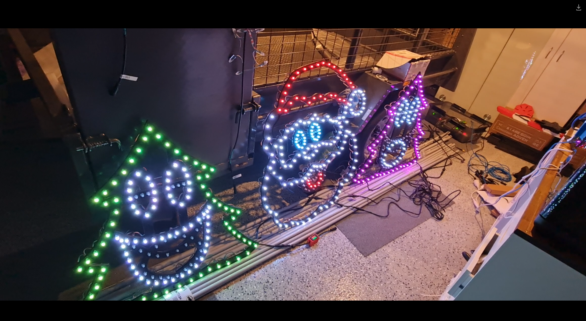
This was certainly something special to see - the props that I'd been working hard on are finally doing exactly what I asked them to do. It's the same sort of satisfaction one gets out of writing code that "just works" - but this felt different. Perhaps the last time I felt this level of accomplishment might stem all the way back to 2016 during the Tour de France live racing project I was part of. Unfortunately it was also short lived when a second sequence I launched caused some significant flickering and colour changes that I thought I knew the answer to.
Now the problem when you watch several hundred YouTube videos on the trials and tribulations of lighting displays, you might be forgiven to thinking you know the answer to any number of problems you may experience. The obvious answer to me was power injection - but I had a T Junction between each of these props, so that shouldn't have been a problem (you can see in the image above the little red volt ammeter box I made in the previous post). While there was an expected voltage drop, the power injection should have absolutely compensated for it. In fact, I even set the brightness from 30% up to 60% expecting a number of pixels to go red (first one to light in a chain) but nope - the flickering didn't seem any worse or better.
The next thing I tried was to swap over the power injection wires in case I had butchered something in the wiring process. I have a collection of 2 pin and 3 pin cables - so swapping these out might also help. Nada. Changed ports on the Power Distribution modules in the power boxes - still the flashing exists. It was getting late so I gave up for the night only to revisit thinking that maybe it requires a signal boost. I'm still not sure why I thought that'd be necessary - after all, each "pixel" should 'regenerate' the ws2811 signal relative to ground so perhaps that was it - but again, power injection should fix that. Several other fixes later, and I tried to work out why one sequence worked and all of the others didn't. Honestly I should have spent more time on this aspect than the others. After watching a few more videos about how the WS2811 signal works (keeping in mind I don't have an oscilloscope), it would appear that if I simply changed the number of output pixels, the flashing would go away (albeit the left hand tree wouldn't light up at all).
Years of problem solving suggests go back to basics and find the odd thing out. The main difference here is that one sequence worked and the other didn't. When I disconnected the left tree, the middle Santa still flickered on that particular sequence so maybe there's something to do with the controller or that sequence. Now, I've been sequencing at 40fps "just because" and never gave it much thought as to how the data would get to the pixel to light up correctly. The 40fps means there's 25ms to process all the data required to light up some 800 pixel x 3 LEDs per pixel. That leaves around 0.0104ms or about 10 microseconds per frame (or 30 microseconds per pixel). So... if you have 800 pixels, and your controller can't quite push 30 microseconds per pixel, you're going to get some corrupted data. In this case, that corrupted data might very well be within lights towards the end of your 'string'. So armed with this thought, I changed the port to rule out a dodgy PWM pin, and sure enough - at 40fps, all three props lit up perfectly and all in sync. To rule out the controller board, I also tested another Raspberry Pi and sure enough - that worked fine on both ports. So yay - on one hand I resolved the issue and on another - I've got a Raspberry Pi 4 that can only push around 400 pixels at 40fps due to something not quite right on this one PWM pin.
Power Distribution
I touched on power distribution last time, but suffice to say I now have two power distribution boxes set up - one for the roof to control the LEDs on the upper half, and one for the ground to do the LED strips, light up props and matrix.
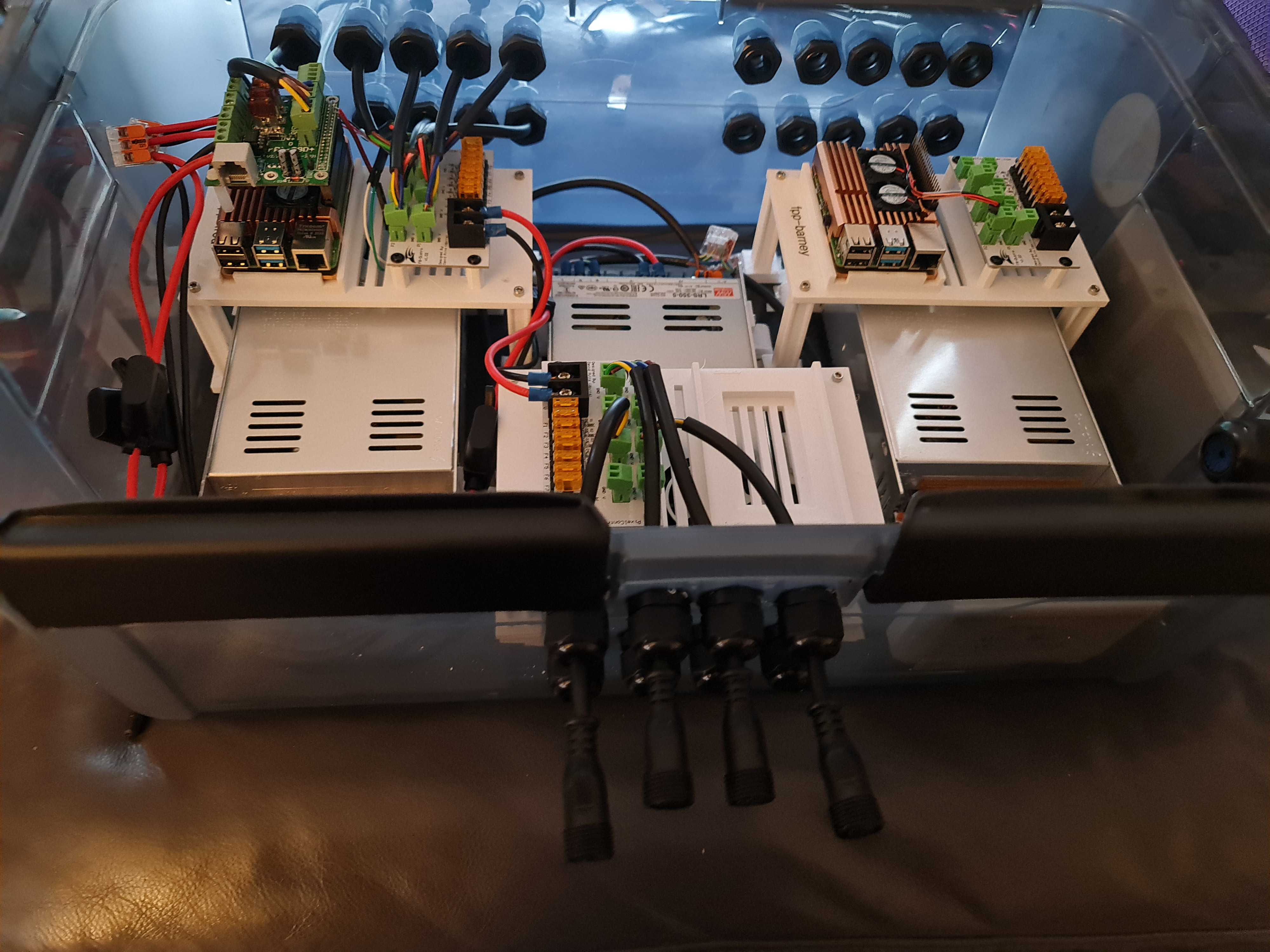
I won't spend a lot of time posting about it - there are plenty of nicer boxes on YouTube and Facebook for this sort of thing but the basics of this setup include:-
- Raspberry Pi 4 with RPi-28D+ capes to run 800 pixels per port (see that flickering post above).
- An 8 port Power Distribution Board
- Either 12V or 5V Power Supply depending on which side of this box I'm plugging stuff into.
In addition, there's a Cat6 socket that plugs into a Ubiquiti Flex Mini switch that's USB-C and POE Powered (yay! found a use for another draw hog) - so these will work nicely under the roof line. To help with some electrical safety here, each input and output is 'fused' to their correct rating - the idea being if we get a short, we'll reduce the risk of something burning.
That's probably all I'll say about this - I wouldn't want you taking electrical advice from a software developer.
Building the PVC Matrix
Ok - so here's an interesting one born out of some ideas borrowed from this video. This is going to be a 50 x 20 pixel matrix cut into 2.5m sections and 5cm spacing. I mocked up several 3D Printed designs - which frankly have been useful but a total waste of time (even when printed at 100% infill, the ABS just isn't quite strong enough to hold the PVC Pipe in place. I also didn't have a drill press, so having 3D printed drill guides helped create some kind of straightness although far from perfect. After several hours dedicated to drilling holes into PVC, the rest is down to painting.
The video I mentioned earlier makes this look easy - frankly this is perhaps the most annoying of all the props to assemble. After painting, I've managed to scratch the paintwork pretty extensively using my 'rings' that will hold and space the PVC pipes together. It's also been super time consuming. Doing this again, I'd probably opt to look at some of the commercial offerings - whether that's chicken wire with 5cm spacing and 3D print 1,000 mounting circles or something else.
Anyway - pictures on this one to come.